
First I want to explain why I'm posting each section in a separate thread; I actually have two reasons:
- So I can submit a final thread when this is done that will index and link each section.
- So that anyone having problems with the information given in that section can post their questions in that thread. This may help others with similar problems as well.
I also have a second motive for doing this section next. The display anomalies I spoke of in the last section may be a bit more difficult to detect once your bitmap texture is in place. I want everyone following this tutorial to see that these shading anomalies do indeed exist in the DirectX display and they are much more easily seen with a standard PHONG color.
Some will appear to go away after the texture map is applied but they will still be there none-the-less.
______________________________________________
Stock Animations
This is what Microsoft calls animations for parts that are consistent from one aircraft to the next and include things like the Rudder, Ailerons, simple hinged Flaps, etc. Most of these stock animations deal with control surfaces and animations that rotate about a single axis.
In the folder MakeMDL_SDK you will find MakeMDL.doc. Open this document and scroll about half way down the document to find a table list of “Stock Animations (aircraft only)”
Notice the part names!
When MakeMDL.exe runs through the conversion process it recognizes these part name exactly as written in this list. If you make a part named “Aileron Left” it will not animate. If you name it “l_aileron” (as listed in the document) this part will move when you control the aircraft.
MakeMDL doesn't care what comes after the recognized part of the part name. If you attach a foot to the rudder and call it "rudder_L_foot" it will still animate with the rudder controls. Also notice I Capitalized "Rudder". Character case does not matter to MakeMDL for these part names and I could have typed "RUDDER" and it would still work.
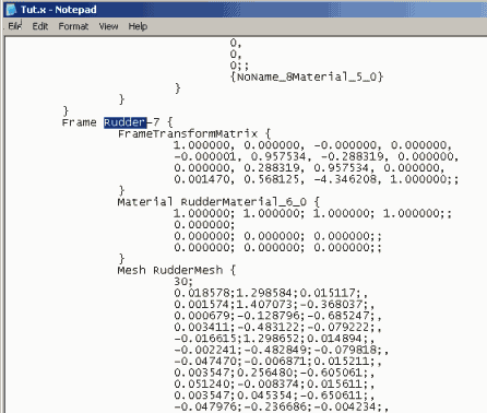
With that in mind I have included a “rudder” with my model:
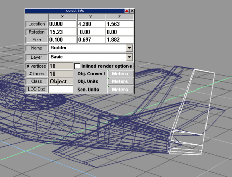
Notice that I have named the part using the tS properties box and named it exactly as listed in the MakeMDL document. In the exported X file for this aircraft, this portion of the mesh will carry the label “rudder” and be recognized by MakeMDL as an animated part.
Flight Simulator knows to rotate this part according to how much rudder is applied in the cockpit and rotates it around it's Z axis. This is not mentioned in the document under “Stock Animation” but the rotational axis is mentioned for several of the other parts in the table listing for “Keyframe Animations” Generally speaking, most horizontally hinged parts such as ailerons, flaps, and elevators, rotate about their X axis.
To make these parts look right when they move you should activate the tS display for the axis of that part and adjust it's position and angle to run along the hinged edge. In this case, think of the Z axis for the rudder as the hinge that attaches it to the vertical stabilizer.
Make sure the Y axis is centered in the rudder's cross section and perfectly parallel with the rudder's centerline (both looking from the "top-down" view). This insures that zero degrees of rudder in the cockpit means a visually centered rudder, and that it rotates from the center of the leading edge rather than from either one of the outside edges.
Once the part is named and axis adjusted select the model as you did befor, beginning with the fuselage first then adding all other parts to the selection, export as X format, run it through MakeMDL and test it in Flight Simulator.
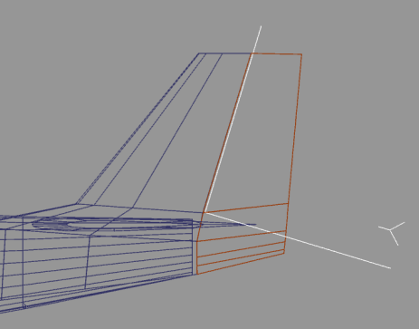
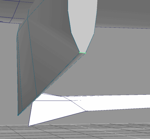
Finally, notice the unexplained shading created by “cutting out” the rudder from the stabilizer. As I've said some of this will go away when the texture map and UV is applied, but some will not. I just wanted you to see it for now. I'll show how to overcome most of these anomalies when we talk about texture and UV application.
One last thing: I got my first MakeMDL error on this model. It was “Co-Located Verticies error #xxx something something something …..
Realizing that I only edited the vertical stabilizer and rudder, I saved the fuselage and rudder only and ran it through MakeMDL to see if I would again get the error, then I did the same for the fuselage and stabilizer and tested it again. While testing like this I save the fuselage also because MakeMDL has a lower vertex number limit for part size. An example of this limit would be converting a single cube. This will cause MakeMDL to error out. I'm not sure of the actual lowest number of vertex it will convert but I seem to remember reading “12” somewhere. ??? And it may actually depend on the number of faces. I just include the fuselage for position and to avoid the lower limit error.
Anyway, the “Co-Located Verticies” error was caused by splitting off the rudder and resulted in a deleted edge between two vertex:
Originally, these two vertex (highlighted - part of the vertical stabilizer) were in close location. When I split off the rudder part of the mesh, it created this gap between the two with no attaching edge. This causes the face to attach itself to some other undetermined or random location and causes this error. I moved them further apart and attached an edge between them, then moved then back into place. This created an edge for the corner and anchored the polygon face and corrected the MakeMDL error.
Post any questions or problems you may be having so far. I will do my best to help clear them up.